calculating OpenGL perspective matrix from OpenCV intrinsic matrix
How can we calculate the OpenGL perpsective matrix, from the camera calibration matrix (intrinsic matrix) and other parameters?
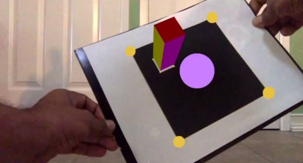
When we develop augmented reality applications, we have to display OpenGL graphics superimposed on the realtime video feed that you get from a camera. To do this we must do two steps:
- We must first calibrate our camera as an offline process to determine the intrinsic parameters of the camera as described by Hartley and Zisserman
- The augmented reality application, on every frame of the realtime video feedback, now uses the intrinsic matrix, and correspondence between the image and object-centric points of a fiducial marker and give you the rotation and translation (model-view matrix) of the OpenGL frame. For drawing an open OpenGL object, we need the current model-view matrix and the perspective matrix. We just mentioned how we can get the model-view matrix. The persective matrix conventionally stays the same for the duration of the application. How do we calculate the perspective matrix, given the intrinsic matrix we got from our camera calibration?
Please checkout my implementation as demonstrated in this video.
Before we must give any explanation, we must acknowledge the following excellent blog post by Kyle Simek which is a more general solution on this subject. What follows is my personal way to explain off the complexity, deriving largely from Kyle’s work, assuming the specialization that the OpenGL view frsutum constructed is symmetrical wrt the co-ordinate axes.
Problem specification
What do we have?
- We have the values from the intrinsic matrix.
- We assume a near and far plane distances and of the view frustum.
- We also assume that the image plane is symmetric wrt the focal plane of the pinhole camera.
- From OpenGL literature(See Song Ho Ahn ), we have the formula for the OpenGL projection matrix as, .
What do we need to find?
- The only unknowns in are and . We need to find them from the above givens, so that we can completely calculate, .
Some basic explanations
Haretley-Zisserman pinhole camera
We have the OpenCV intrinsic matrix to start with. It is expressed as,
Note that, for all our practical purposes , the skew factor is zero. So the above intrinsic matrix simplifies to:
This is derived from the the basic pinhole camera description as shown in fig1 an fig2.
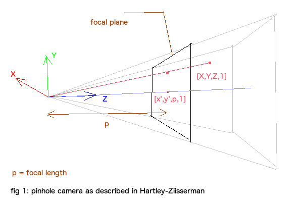 . Note that we use the symbol for focal length,
since the we need to use the regular symbol for the far plane distance later. The transformation that transforms the point in 3d space to the point is a matrix multiplication followed by
perspective division (division of result by the component of the result).
. Note that we use the symbol for focal length,
since the we need to use the regular symbol for the far plane distance later. The transformation that transforms the point in 3d space to the point is a matrix multiplication followed by
perspective division (division of result by the component of the result).
where ‘’ sign captures the perspective division.
Now, let us take a look at the transformation that relates the image (pixel) co-ordinates and the points in the focal plane.
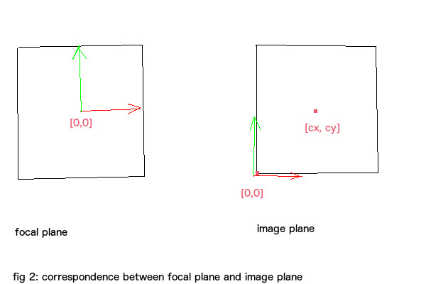
The transformation from focal plane to the image plane is captured by the following matrix.
where
- is the pixel-coordinate/camera-space scale factor along axis.
- is defined similarly along the axis.
- and are points in the image plane corresponding to the origin of the focal plane.
- the image plane origin is at left-bottom corner.
- According to our initial assumption, our image plane is symmetrically arranged wrt to the image plane.
Equations () and () are combined in the following equation.
The upper portion of the above matrix is in fact our intrinsic matrix.
pinhole camera in OpenGL view frustum.
Let us put this pinhole camera in the OpenGL coordinate system, which will help us to visualize the integration of the two (HZ-pinhole camera vs OpenGL} formulations.
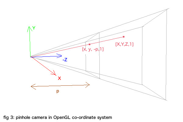
This is different from fig 1 in that, the camera is looking down the negative Z-axis just as in OpenGL. Also, the image plane origin should correspond to the (minimum, minimum) point of the focal plane origin. With these considerations, the effective intrisic matrix in OpenGL co-ordinate system is
The effective intrinsic matrix is unimportant to our eventual calculation.
OpenGL perspective matrix
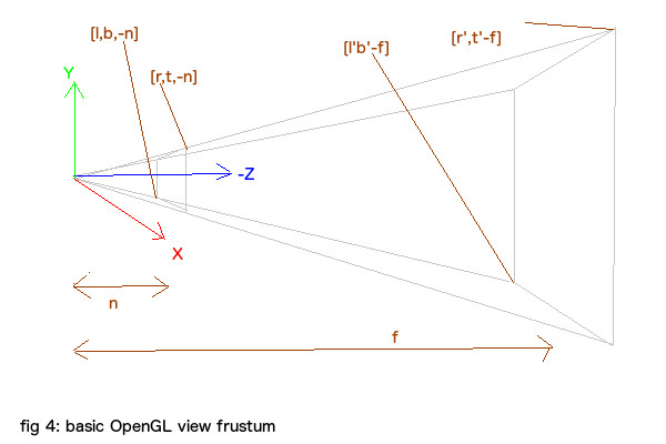
Shown above is the OpenGL view frustum. From this we should be able to generate a pespective matrix. OpenGL will use the perspective matrix to transform a 3d point to the normalized device coordinate space below.
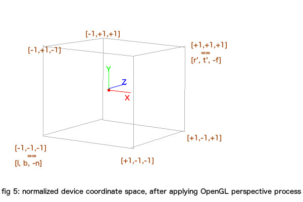
For mathematical sanity, please be assured that and can be computed from and by means of similarity transforms.
We can write the above OpenGL perspective process as
All the components of the resultant vector will be in the range to , (ie: normalized device coordinates). The sign denote division by component. The derivation of is ver well described by Song Ho Ahn and we wont be repeating that. So we can write as,
Specialization of the OpenGL perspective matrix
Please note that, when trying to apply the perspective projection to our needs, the following constraints apply, . Also, we have , and . Also, since our image plane is symmetrically arranged wrt the focal plane, we have , . So we have , , and . So () will simplify to
Result
We assume the values of the near and far planes. So let us say that and are known. (In our implementation we used and .) How can we compute the values of and from the givens?
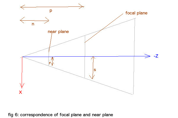
Shown above is a top view of the frustum. The unknown when transformed to the image plane has a value of . So
From the above figure, we have
Hence
Or
Similarly,
So we can write our projection matrix as,
Please checkout the following video.
References
- Kyle Simek’s excellent post on OpenGL-opencv camera calibration
- Song Ho Ahn’s excellent derivation of OpenGL perspective matrix
blog comments powered by Disqus